
Evaporator Cascade Control & PID Tuning
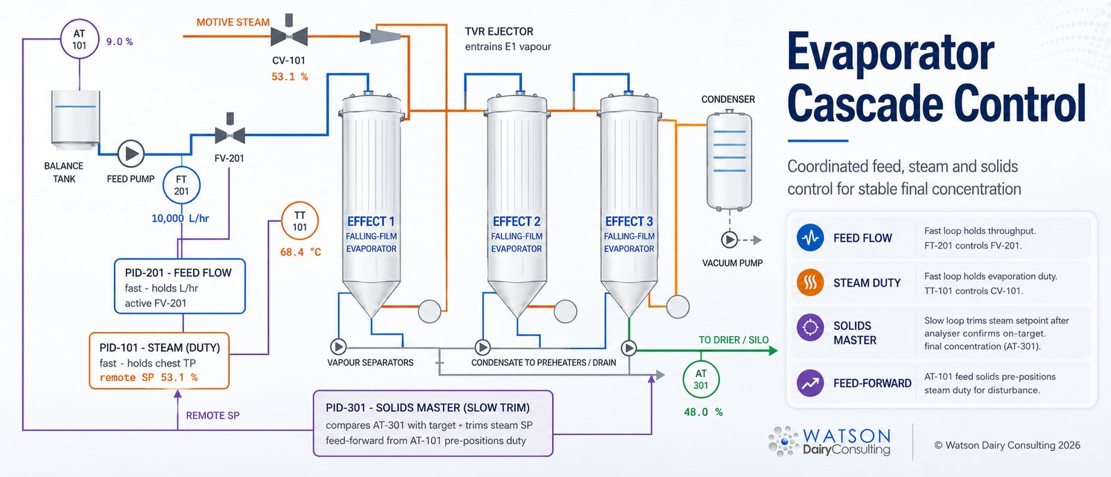
How does a dairy evaporator hold final concentrate solids steady when the feed, the steam supply and the heat-transfer surfaces are all moving? With a cascade of PID controllers plus feed-forward: fast loops steady the plant, a slow master loop trims the target, and feed-forward corrects disturbances before they become errors.
The working model below lets you run it, break it and watch it recover — then the sections that follow explain what each element does and how it is tuned.
Plant mimic — product, vapour & signal paths
Scenarios
Chart recorder — last 180 s
Event log
What Is Cascade Control?
Cascade control is two controllers working in series. The primary (master, or outer) controller looks after the variable that actually matters — here, final concentrate solids — but its output is not a valve position. Its output is a setpoint, handed down to a secondary (slave, or inner) controller, which holds a fast local variable — steam chest temperature or pressure — by driving the steam control valve.
The point of the arrangement is disturbance rejection at source. If boiler header pressure dips, the inner steam loop sees it within seconds and corrects the valve before the disturbance ever reaches the product. Without the cascade, that same dip would have to travel all the way through the evaporator, appear as a solids deviation at the analyser, and only then be corrected — minutes later, and by the wrong amount. The standard design rule is that the inner loop must be substantially faster than the outer loop — a factor of three to five is the commonly quoted minimum — so the master can treat the tuned inner loop as just another well-behaved part of the process.
Why an Evaporator Needs It: Sensitivity and Dead Time
Two properties of a falling-film evaporator make single-loop control of final solids a losing game.
1. Final solids are hypersensitive at high total solids. This falls straight out of the mass balance. Take the model's numbers: 10,000 L/hr of skim at 9.0% total solids is roughly 10,330 kg/hr of feed (density ≈1.033 kg/L) carrying 930 kg/hr of solids. To reach 48% solids, the concentrate stream must be 930 ÷ 0.48 = 1,937 kg/hr, so the evaporator removes about 8,393 kg/hr of water. Now increase evaporation by just 100 kg/hr — barely 1.2% more duty. The concentrate stream shrinks to 1,837 kg/hr and final solids jump to 930 ÷ 1,837 = 50.6%. A 1.2% change in evaporation moved final solids by 2.6 percentage points. The closer you concentrate towards the product's limit, the steeper this gets — small duty errors produce large solids errors.
2. The measurement arrives late. Product leaving the last effect takes time to reach the concentrate analyser, and the analyser (refractometer or density meter) has its own response lag. The master controller is therefore always reacting to what the plant was doing some time ago — in the model, 12 seconds; on a real plant it depends on line lengths, hold-up and instrument type. Dead time is the hardest dynamic to control against: no amount of clever tuning removes it, and a controller tuned faster than the dead time allows will chase its own tail and oscillate the entire train. Run the “raise target” scenario above and watch the two green pens — the master literally cannot see the result of its action until the delayed pen catches up.
The Three Loops in the Model
PID-201, feed flow (fast). Holds evaporator loading at the set L/hr so residence time, tube wetting and the heat balance do not drift. Tube wetting is protected first; everything else is trimmed around a steady feed. Flow loops are fast, noisy and almost always run as PI controllers.
PID-101, steam chest (fast). Holds calandria temperature or pressure by moving CV-101, giving a stable, repeatable evaporation duty for whatever setpoint it is handed. It neither knows nor cares what the solids are — that is the master's job.
PID-301, solids master (slow). Compares the concentrate analyser AT-301 against target and gently trims the steam setpoint; on many plants it can also bias product withdrawal. Because of the dead time and the sensitivity shown above, it runs with low gain and integral-dominant action — deliberately patient.
Feed-Forward: Correcting Before the Error Exists
Feedback control has a built-in weakness: it cannot act until an error has already appeared. On an evaporator, the biggest routine disturbances — feed solids and feed flow — are both measurable at the inlet, minutes before their effect reaches the analyser. Feed-forward exploits that: measure the disturbance, recalculate the evaporation required to hit target from the mass balance, and reposition the steam demand immediately. Required evaporation is simply:
where F is the feed mass flow and X the solids fractions. When feed solids step from 9.0% to 8.2% in the model with feed-forward on, the duty is repositioned within seconds and solids barely dip; with it off, nothing happens until the deviation crawls through the dead time to AT-301, and the excursion is roughly twice as deep and far longer. No feed-forward model is perfect — density assumptions, heat losses and flash all drift — so the feedback master stays in the scheme to trim the residual error. Feed-forward does the heavy lifting; feedback mops up.
PID, In Plain Terms
A PID controller computes its output from the error e(t) — the gap between setpoint and measurement — using three actions. In the ISA standard form:
Proportional (Kc, or proportional band). Output moves in proportion to the current error: bigger error, bigger correction. On its own it always leaves a standing offset, because zero error would mean zero corrective action. Note that many systems specify proportional band (PB% = 100/gain) instead of gain — a higher PB is a weaker controller. Check which convention your system uses before touching anything.
Integral (Ti, “reset”). Accumulates the error over time and keeps pushing until the error is exactly zero — this is what removes the proportional offset. Units are a second trap: some vendors use minutes per repeat, others repeats per minute — one is the reciprocal of the other, and entering a value in the wrong convention makes the loop dramatically faster or slower than intended. Integral action also brings windup: if the valve saturates (fully open, say, during start-up), the integral keeps accumulating a correction it cannot deliver, then massively overshoots when the process recovers. Any properly configured controller needs anti-reset-windup, which freezes or limits the integral term while the output is saturated.
Derivative (Td). Responds to the rate of change of the error — in effect, a prediction of where the error is heading. It can add useful damping on clean, slow signals such as some temperature loops, but it multiplies measurement noise straight into the valve, and it cannot see through dead time. On flow loops and analyser-based loops it is normally left off: the model's solids master and feed loop are PI, which reflects standard dairy practice.
Two configuration details matter as much as the tuning numbers. Controller action (direct/reverse) must match the process — more steam means higher solids, so the solids master is reverse-acting on a rising measurement. And in a cascade, the slave setpoint must track while the master is in manual so that switching back to cascade is bumpless — no step to the valve at the moment of transfer.
Tuning a Cascade, Practically
Inner loop first — always. Put the master in manual, give the slave a local setpoint, and tune it for a fast, well-damped response to setpoint steps. Only then close the outer loop and tune the master against the now-predictable inner loop. Tuning both together, or the outer first, produces interactions that are near-impossible to diagnose.
For the numbers, the classic starting point is Ziegler–Nichols (1942) — find the ultimate gain and period, then back off per the published rules. It remains a useful benchmark but is deliberately aggressive (quarter-amplitude damping) and copes poorly with dead-time-dominant loops. For an evaporator solids master, lambda (IMC-style) tuning is the better fit: choose the closed-loop response time you actually want — comfortably slower than the dead time — and derive gain and integral from the process model. The practical recipe for the solids master is: filter the analyser signal, use PI only, keep gain low, let integral do the work, and accept that the loop is slow by design. A solids master that looks impressively busy is a solids master that is about to oscillate.
And know what tuning cannot fix. As the calandria fouls, the same valve opening evaporates less, solids sag, and the master quietly raises steam demand to hold target. Duty creeping upward at constant throughput and target — with steam economy falling in step — is the fouling signature, visible in the model's fouling scenario. That is a CIP and heat-transfer problem; retuning the controller merely hides it until the valve runs out of travel.
Fault-Finding Quick Reference
| Symptom | Most likely cause | First check |
|---|---|---|
| Final solids oscillate slowly, whole train breathing | Solids master tuned too fast for the dead time | Halve master gain / lengthen integral; confirm analyser dead time |
| Large, slow solids excursions on every feed change | No feed-forward, or feed-forward disabled/mis-scaled | Verify AT-101/FT-201 inputs and the feed-forward calculation |
| Steam duty creeping up over days at constant rate and target | Fouling — falling heat-transfer coefficient | Trend duty and steam economy; review CIP, not the tuning |
| Valve slams on switching master to cascade | No setpoint tracking — transfer is not bumpless | Enable slave SP tracking / controller initialisation |
| Huge overshoot after start-up or a trip | Integral windup while the valve was saturated | Confirm anti-reset-windup is configured and working |
| Solids loop jittery, valve constantly dithering | Analyser noise reaching the controller (worse if derivative is on) | Filter the measurement; switch derivative off |
Evaporator Cascade Control & PID FAQs
What is cascade control on an evaporator?
What is the difference between the master and slave loop?
Why is the final solids loop deliberately slow?
What is feed-forward control and why use it on an evaporator?
What do P, I and D actually do?
In what order do you tune a cascade?
Why does derivative action rarely help on a solids loop?
Can control tuning compensate for evaporator fouling?
Selected References
- Ziegler, J.G. & Nichols, N.B. (1942). Optimum settings for automatic controllers. Transactions of the ASME, 64, 759–768.
- Åström, K.J. & Hägglund, T. (1995). PID Controllers: Theory, Design, and Tuning, 2nd ed. Instrument Society of America, Research Triangle Park.
- Seborg, D.E., Edgar, T.F., Mellichamp, D.A. & Doyle, F.J. (2016). Process Dynamics and Control, 4th ed. Wiley, Hoboken.
- Shinskey, F.G. (1996). Process Control Systems: Application, Design, and Tuning, 4th ed. McGraw-Hill, New York.
- Westergaard, V. (2004). Milk Powder Technology: Evaporation and Spray Drying, 5th ed. GEA Niro A/S, Copenhagen.
- Walstra, P., Wouters, J.T.M. & Geurts, T.J. (2006). Dairy Science and Technology, 2nd ed. CRC Press, Boca Raton.
- ANSI/ISA-5.1-2009, Instrumentation Symbols and Identification. International Society of Automation.
Related pages: Evaporator Training · Evaporator Mass & Steam Balance Calculator · Evaporator Steam Economy Calculator · Milk Powder Production · Spray Dryer Training · Dairy Process Optimisation
Commissioning an evaporator, fighting an unstable solids loop, or training operators on evaporator control? Watson Dairy Consulting provides independent evaporator troubleshooting, control philosophy review and hands-on operator training — independent of any equipment vendor or systems integrator. Please contact us to discuss your requirements.
Discuss Your Evaporator ProjectFurther reading: John Watson publishes articles on dairy industry topics on LinkedIn — from infant formula safety and milk supply to plant design, yield improvement and dairy commodity outlook. Browse all articles by John Watson on LinkedIn →
John Watson
Office: +44 1224 861 507
Mobile: +44 7931 776 499
jw@dairyconsultant.co.uk
We are a longstanding member of the Society of Dairy Technology
and have Fellowship of the Institute of Food Science and Technology.



Contact Details
John Watson
Office: +44 1224 861 507
Mobile: +44 7931 776 499
jw@dairyconsultant.co.uk
What Our Clients Say
We are a longstanding member of the Society of Dairy Technology
and have Fellowship of the Institute of Food Science and Technology.
Locations

Services
Enquiry Form

